
Bore and stroke in millimeters. Ring gaps in millimeters. Two things decide the correct gap, every time: engine category (Turbo, Turbo Race, or Aspirated) and cylinder material (Cast Iron or Aluminum). Don’t assume cast iron by default — always confirm the block material first.
General rules — apply to every category and material
- Use a torque plate to take correct measurements. A bare block reads differently than a bolted-down head.
- Rings must never exceed the calculated engine stretch, even with the cylinder torqued.
- Measure every gap with a feeler gauge — don’t eyeball it.
- General tolerance on the numbers below: -0.05mm / +0.10mm.
- The oil ring (3rd ring) minimum gap must never be filed open to hit spec. If it doesn’t meet the minimum as supplied, the ring is the wrong part for that application — replace it, don’t file it.
Cast Iron Cylinders
| Category | 1st Ring | 2nd Ring | 3rd Ring (oil) |
|---|---|---|---|
| Turbo | Bore × 0.005mm | 1st ring + 0.1mm | Min. 0.55mm — do not file |
| Turbo Race | Bore × 0.006mm | 1st ring + 0.1mm | Min. 0.60mm — do not file |
| Aspirated | Bore × 0.004–0.005mm | 1st ring + 0.1mm | Min. 0.38mm — do not file |
Aluminum Cylinders
| Category | 1st Ring | 2nd Ring | 3rd Ring (oil) |
|---|---|---|---|
| Turbo | Bore × 0.0040mm | 1st ring + 0.08mm | Min. 0.44mm — do not file |
| Turbo Race | Bore × 0.0048mm | 1st ring + 0.08mm | Min. 0.48mm — do not file |
| Aspirated | Bore × 0.0032–0.0040mm | 1st ring + 0.08mm | Min. 0.30mm — do not file |
How to read the formula
“1st Ring: Bore × 0.00Xmm” is a per-mm-of-bore multiplier, not a fixed number:
Ring end gap (mm) = cylinder bore diameter (mm) × factor
Worked example — Turbo Race, aluminum block, 88mm bore:
- 1st ring: 88 × 0.0048 = 0.42mm
- 2nd ring: 0.42 + 0.08 = 0.50mm
- Oil ring: flat 0.48mm minimum, never filed open
- Apply the general -0.05/+0.10mm tolerance on top of each computed value.
The oil ring is a flat minimum regardless of bore — it does not scale with diameter the way the 1st and 2nd rings do.
Total Seal Gapless Top — Ring Gaps
For piston kits running Total Seal’s Gapless Top ring (see Total Seal Piston Rings), use the table below — Total Seal’s own published figure plus DP’s own +0.0005 margin on top.
| Application | Fuel | Top Ring Gap |
|---|---|---|
| Street, strip, circle | Gas, Alky, E85 | Bore × 0.0070mm |
| Nitrous up to 150HP | Gas, Alky, E85 | Bore × 0.0075mm |
| Nitrous 150HP-350HP | Gas, Alky, E85 | Bore × 0.0080mm |
| Nitrous 350HP+ | Gas, Alky, E85 | Bore × 0.0085mm |
| Mild boost up to 15lb | Gas, Alky, E85 | Bore × 0.0075mm |
| Medium boost 15-30lb | Gas, Alky, E85 | Bore × 0.0080mm |
| High Boost 30lb+ | Gas, Alky, E85 | Bore × 0.0090mm |
| Mild boost up to 15lb | Nitro | Bore × 0.0080mm |
| Medium boost 15-30lb | Nitro | Bore × 0.0090mm |
| High Boost 30lb+ | Nitro | Bore × 0.0100mm |
Worked example — Street/strip/circle, 88mm bore: 88 × 0.0070 = 0.616mm.
Gapless Top Ring — Installation Orientation
Source: Total Seal installation instructions.
- Install the machined ring first, groove side down, gap 180° from the 2nd ring end gap.
- Install the rail into the groove machined in the ring, with gaps opposed 180°.
The gapless ring is a two-piece assembly — a machined ring plus a rail — and each has its own end gap. Per Total Seal: the rail end gap can be larger than the primary ring’s, but never smaller. The gapless ring is always installed rail side down.
Base source: Total Seal Recommended Gap Chart (Top Ring figures above include DP’s own +0.0005 margin on top of Total Seal’s published numbers). Total Seal’s own disclaimer: “These are general gapping recommendations and are not to be considered absolute. State of engine tune, operating environment and personal experience must also be considered. If for any reason you are in question of these general guidelines, please call or e-mail us prior to final assembly.” Total Seal support: 800-874-2753 or 623-587-7400, info@totalseal.com.
Ring gap position diagram
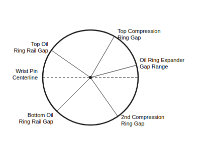
Correct gap orientation around the piston: Top Compression Ring Gap, Oil Ring Expander Gap Range, 2nd Compression Ring Gap, Bottom Oil Ring Rail Gap, Top Oil Ring Rail Gap — all positioned relative to the Wrist Pin Centerline.